
Based on the operating principle, the CCDs are categorized in four major classes:
-linear CCDs
-interline CCDs
-full frame CCDs
-frame transfer CCDs
© Copyright 2010 www.spacealliance.ro
Based on the operating principle, the CCDs are categorized in four major classes:
1. linear
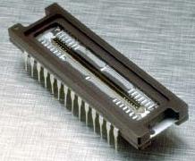
A linear CCD is actually consisting in a single row of pixels which needs to be repositioned by a special mechanism in order to construct the image. By that is a complex system which means is slower and leaves the possibility of potential failures
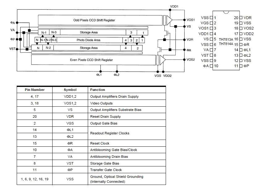
Bellow is an example of this architecture-Atmel TH7813 CCD chip
 credit Atmel
2. interline
credit Atmel
2. interline
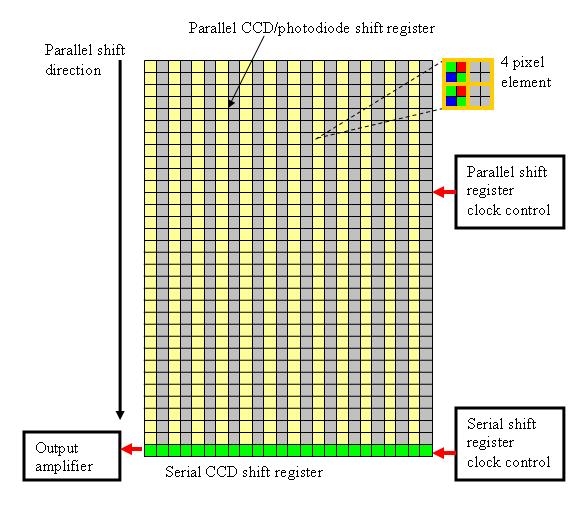
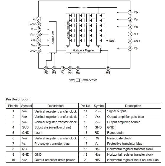
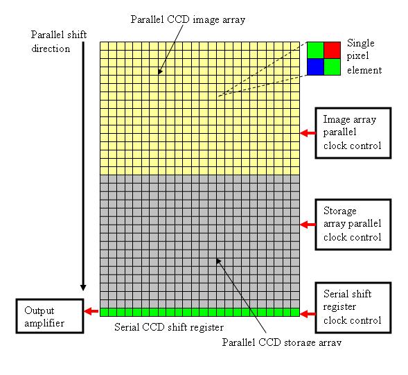
An interline CCD consists in pixels which have both a photodetector and a charge storage area which is formed by shielding or masking part of a pixel from light and using it only for the charge transfer process.
Combined together all these pixels form vertical columns that run from the top of the array to the serial register. Active photodiodes (the un-masked ones) collect the incoming light and then the collected and converted electrical signal is quickly shifted in a parallel transfer to the adjacent CCD storage area of each pixel element (the masked grey area). From there rows of image information are read in a parallel fashion, one row at a time, to the serial shift register.
The serial register takes control and sequentially shifts each row of image information to an output amplifier as a serial data stream.
The sequence is repeated until no rows of data are left.
The major advantage of this technique is the lack of the shutter which means it can achieve faster speeds and frame rates, and elimination of the smear effect mainly due to the high speed in which the image transfer occurs.
However this does not come without a price and this is translated mainly in a complex manufacturing architecture, image lag and lower sensitivity of the sensor. To overcome this problem the designers are usually mounting microlenses on the photodiode array which increase the amount of light entering each element up to 75%.
Bellow is an example of this architecture-
 3. full frame
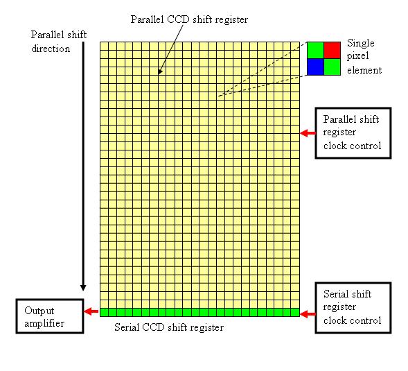
In the case of full frame CCDs the entire surface of a pixel is used for capturing but, since during transfer periods the pixel is busy and cannot contribute anymore to the picture acquisition and in order to prevent an accidental signal to be read, a shutter is placed before the CCD preventing this event.
These masked areas for each pixel form a vertical charge transfer channel running from the top of the array to the horizontal shift register.
During the reading cycle, image is read using two registers coordinated by two clocks one for the parallel shift and the other one for the serial shift. First the image is transferred row by row in the parallel shift direction to the serial register. The serial register then sequentially shifts each row of image information to an output amplifier as a serial data stream. When the serial register is empty a new row is transferred to it and the process is done again until all rows have been redirected to the output amplifier and off the chip to a analog-to-digital signal converter integrated circuit.
The only inconvenient of this technology is the smearing effect which can appear sometimes due to the fact the CCD array is used both as a photodetector and readout mechanism, so when the pixels are by mistake exposed to the light during the parallel readout they will accumulate additional charges.
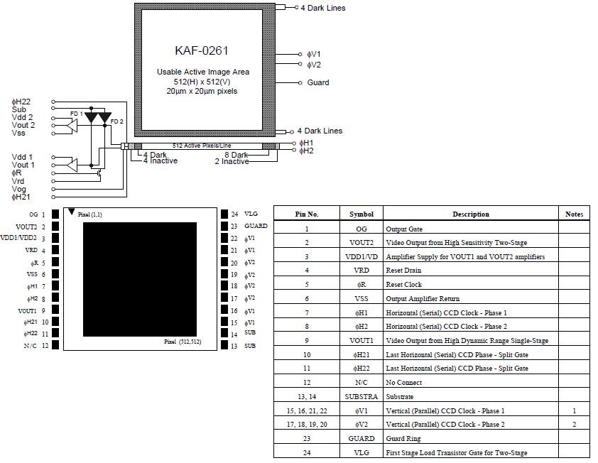
Performances of these CCDs depend directly by the output amplifier bandwidth and the conversion speed of the analog-to-digital converter. Sometimes, in order to increase the quantum efficiency a back illumination solution is put in place light entering the CCD silicon substrate from the rear.
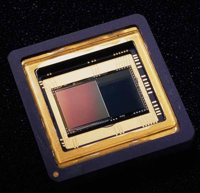
Bellow is an example of the Kodak KAF0261 E type CCD:
 credit Kodak
4. frame transfer
credit Kodak
4. frame transfer
In full frame CCD operation, the CCD must alternate between exposure and readout. During that readout period the CCD continues to remain sensitive to light so a mechanical shutter is used to prevent additional exposure which means the time necessary to open and close the shutter is contributing to the time of CCD readout reducing drastically the percentage of time available for exposure.
The maximum frame rate is also limited by the shutter which means for a given pixel readout rate the only way to achieve a faster frame rate is to lower the exposure time with a direct impact on the quantity of signal the CCD records and therefore to the sensitivity. More than this, events which occurs during readout will be missed completely. Additionally as the frame rate increases the lifetime of the mechanical shutter becomes a major problem.
Frame transfer CCD do not suffer from this problem as only half of the CCD is exposed at a time to light. The other half is masked and is used temporarily to store the images. Once the image –now in the form of electrical charge- is shifted the image area of the CCD can start collecting the next frame while the storage area is read out and digitized.
The main advantages of frame transfer operation are:
-continuous light collection which means the system is more sensitive and will not miss some intermediate events
-readout and light collection are simultaneous which means for a given resolution and pixel rate, frame rates are higher
-a mechanical shutter is not required so reliability is higher
-the system is able to capture two images in rapid succession
The main disadvantages are:
-detection area is usually smaller as they need to accommodate both the photosensitive array and the storage array
-there can be smearing effects on the image during the frame transfer if the illumination is continuous
Like the full frame CCD, the frame transfer ones use two types of registers, a parallel and a serial one, operated by a parallel and a serial clock, but they only apply to the storage area. The mechanism is similar but while the parallel readout is performed on the storage array, the image array is busy to integrate charge for the next image frame.
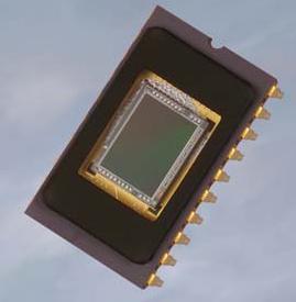
Bellow an example of this architecture- Atmel TH7891 CCD
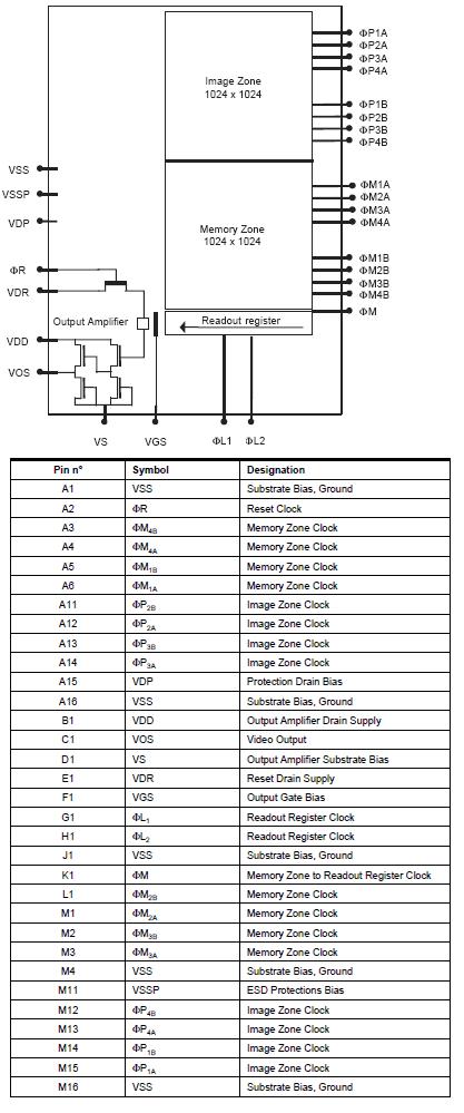 credit Atmel
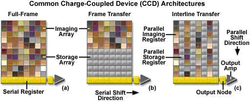
Next picture summarizes in a parallel overview, the most common CCD types used as they have been presented before
Separate of this functionality criteria there are some extra criteria for categorizing the CCDs:
1. based on the gate electrode
-single layered metal gate
-single layered polysilicon gate
-multiple layered polysilicon gate
2. based on the channel type
-p type
-n type
3. based on the channel depth
-surface channel (SCCD)
-buried channel (BCCD)
4. based on the driving method
-normal phase (2,3,4 or more phases CCD)
-pseudo phase
-ripple transfer
-accordion transfer